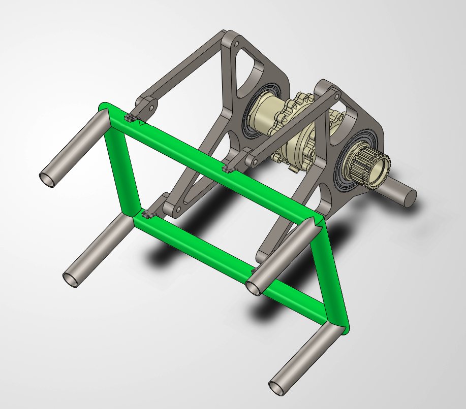
FEB Differential Mount
Formula Electric at Berkeley — Powertrain · 2026
Designed a differential mounting assembly for Formula Electric at Berkeley's chain-driven rear drivetrain — an EMRAX 228 motor driving a Drexler FSAE differential through a 3.53:1 reduction. The assembly includes bearings, fasteners, frame tabs, a jacking bar and a chain tensioner, and was verified in SolidWorks FEA to a 1.5 minimum factor of safety under 4G shock loading.
Requirements & Hand Calculations
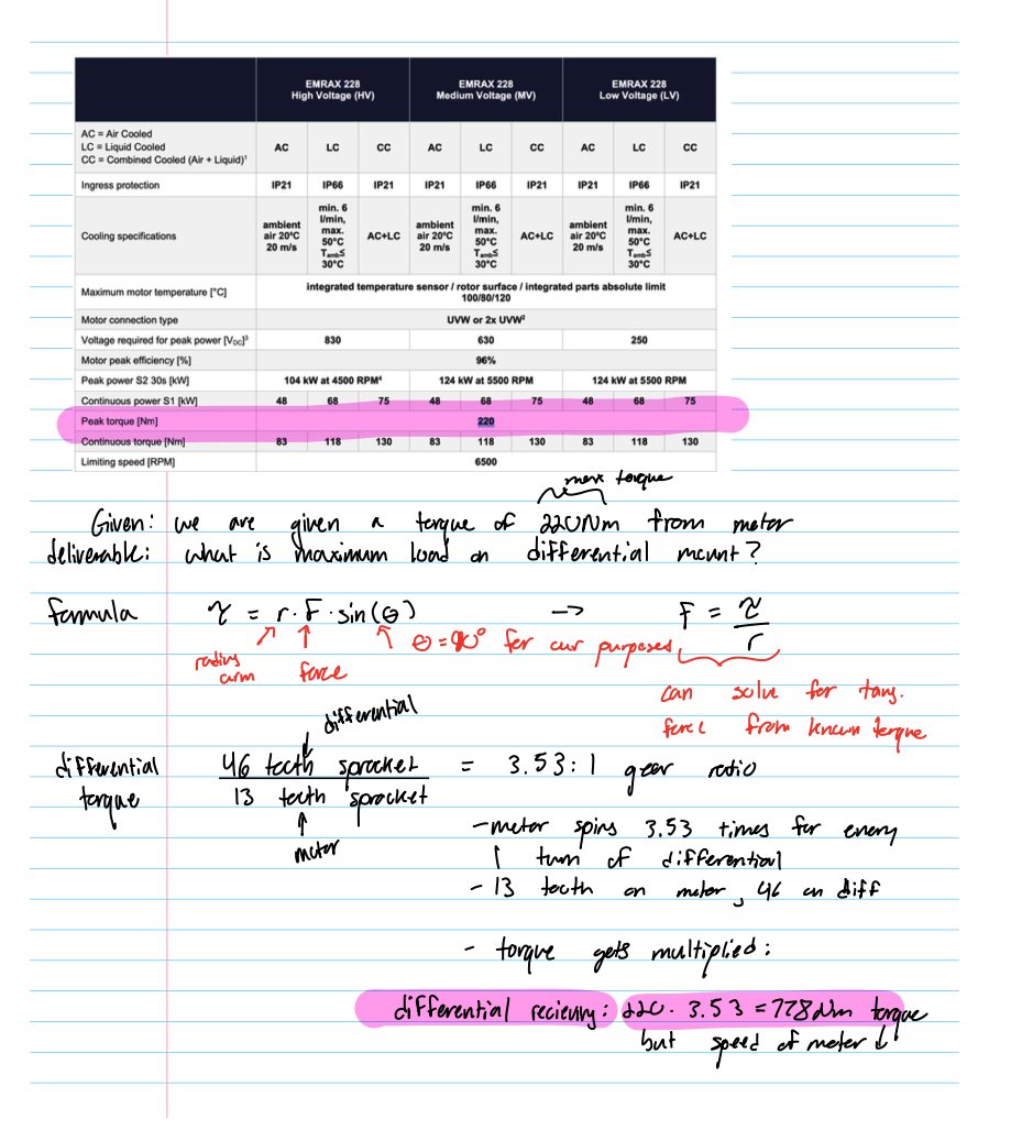
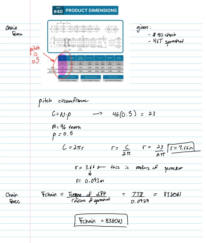
Started from the FSAE rules and the team's project brief: calculate the maximum load on the differential, mount it securely to the rear chassis with all required hardware, add a rules-compliant jacking bar, and compare chain-tensioning options (turnbuckle, eccentric, idler sprocket). From the motor's peak torque and the gear ratio I found the torque on the Drexler differential, then used the #40 chain and sprocket radius to convert that into an 8.4 kN tangential chain load on the mount.
Preliminary Sketches
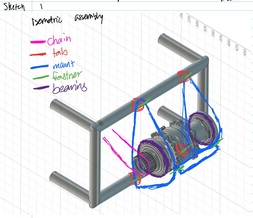
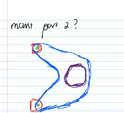
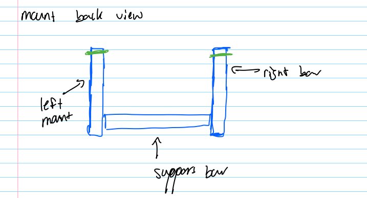
First sketches to envision the mount system before opening CAD — chain in pink, tabs in red, mount in blue, fasteners in green, bearings in purple. The idea: two mounting brackets cross-supported by a bar, mounted to the chassis via welded tabs, with tie rods used to adjust chain tension. These sketches were what I brought to office hours with senior team members.
SolidWorks Design
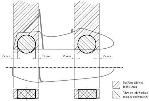
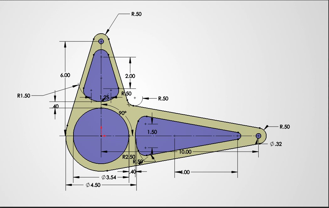
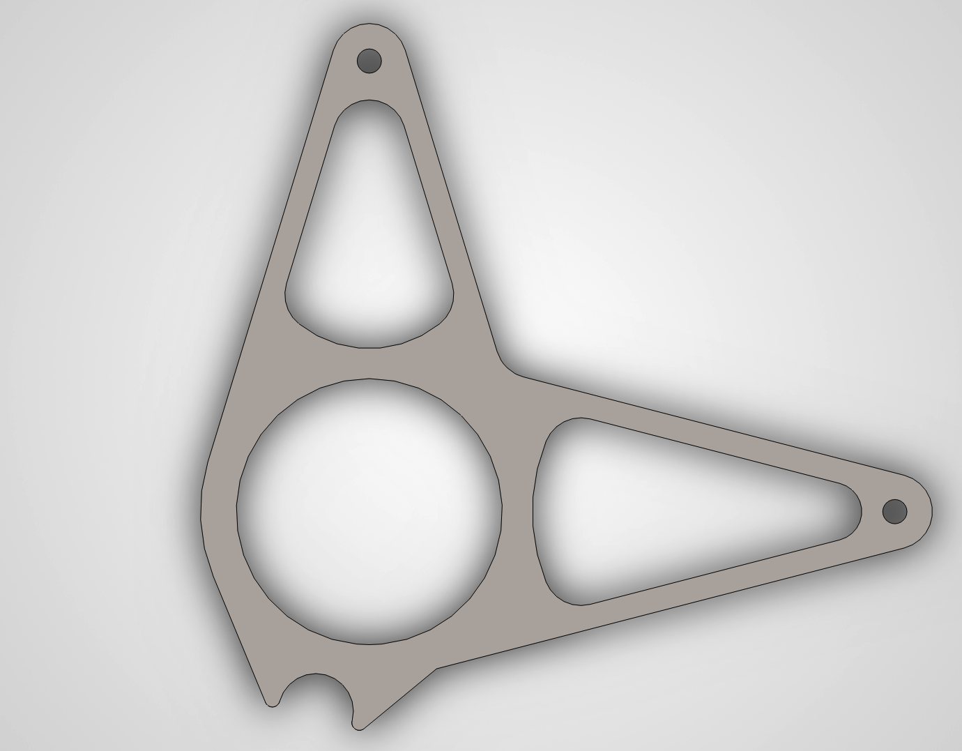
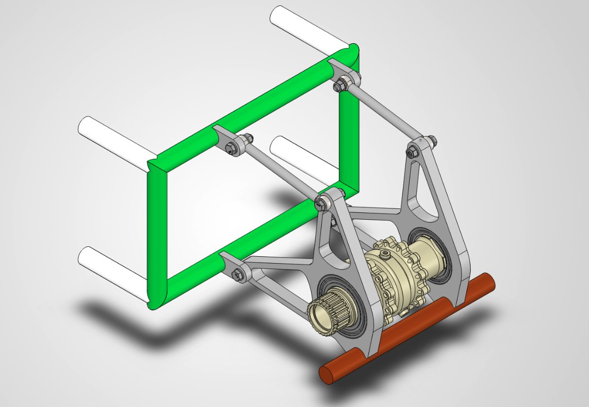
Built two mounting brackets with fully defined sketches and repeatable dimensions — identical except for the bearing bore, since one side carries a smaller bearing. A bottom tooth mounts the jacking bar, and material was cut out of the bracket wherever it didn't carry load. The assembly was designed to minimize unique parts: 4× frame tabs, 2× tie rods, 80 mm and 90 mm brackets, a jack bar, and 4× M8 bolts with locknuts. Screwing the tie rods in or out moves the differential ±1 in for chain tension.
Simulation
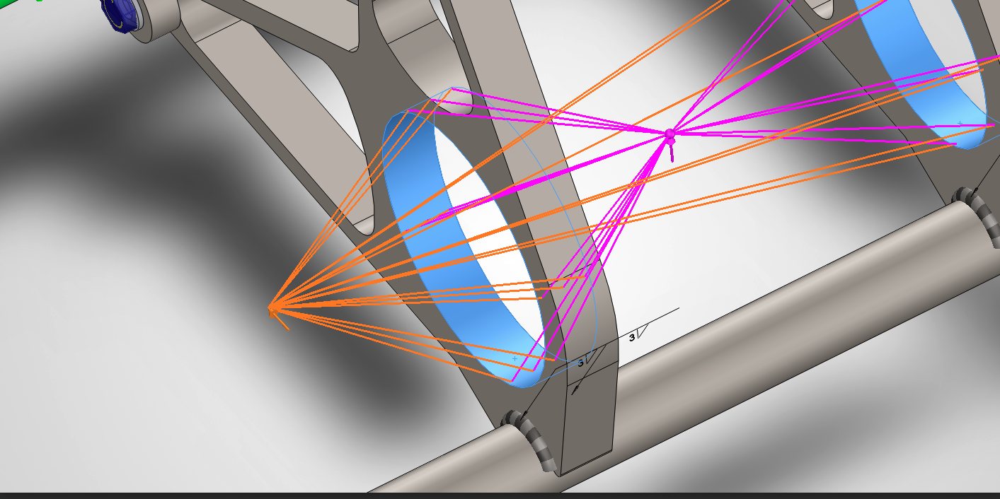
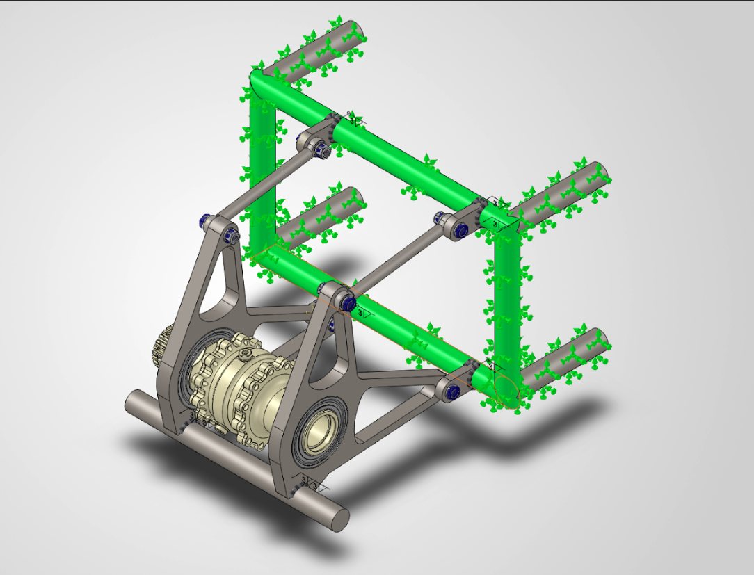
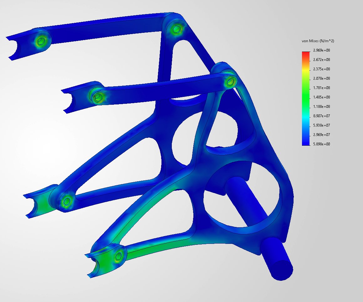
Tie rods were simplified as tabs of equivalent length, the tube chassis was used as the fixture, and all M8 hardware was modeled as bolted connections so hardware stress showed up in the results. Added the differential weight and the 8.4 kN chain force as remote loads, applied the weld tool to every welded item, assigned materials and generated the mesh.
Analysis Results
- Applied an 8.4 kN chain load to the differential mount
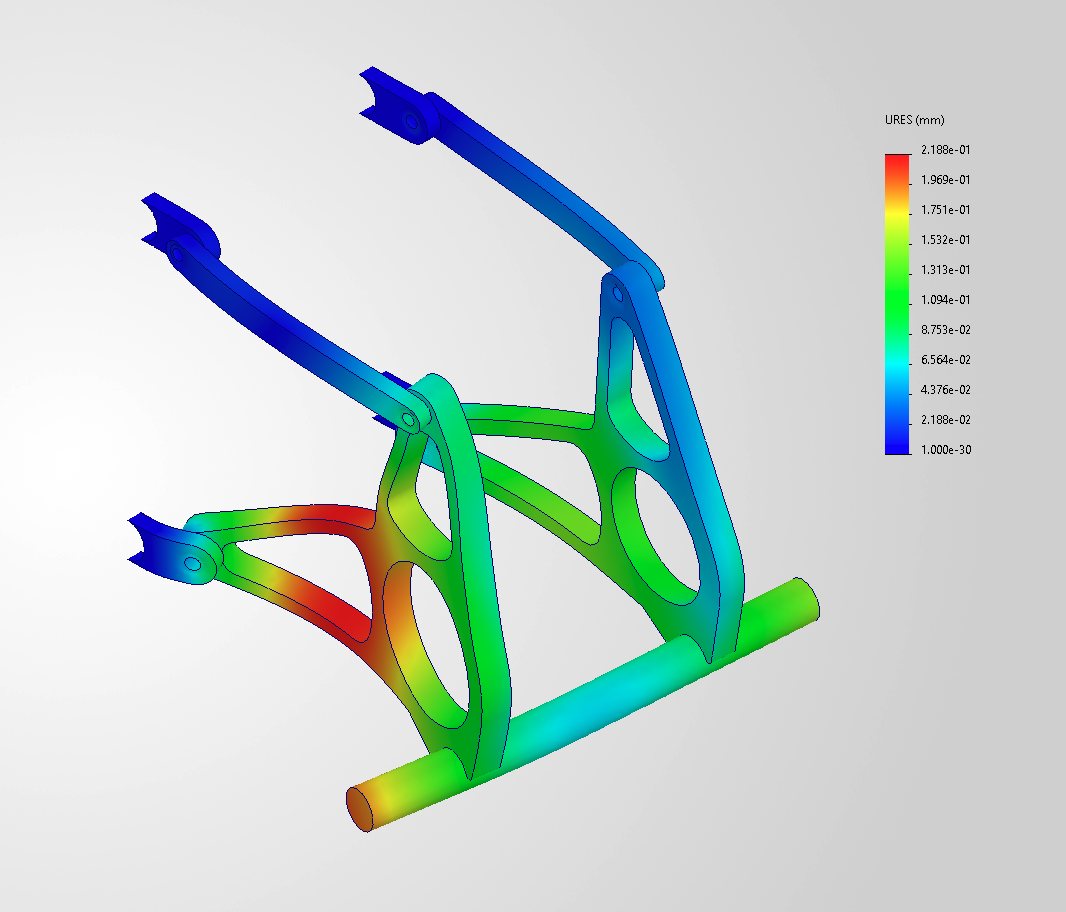
- Maximum displacement of only about 0.22 mm
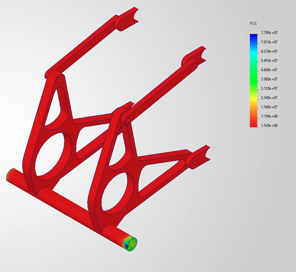
- Minimum factor of safety of 1.549 — meets the 1.5 target for this load case
Materials, Cost & Manufacturing
Chose AISI 4130 steel: strong and stiff enough for the differential and chain loads, easy to weld to the steel chassis and jacking bar, and low cost with room to remove material later. Tabs are laser or water cut and drilled, the jacking bar is chop-sawed, bearing bores and critical holes are CNC machined, and the final assembly is bolted and welded. Next steps: more FEA iterations to cut weight while keeping FOS near 1.5, more realistic contacts and load cases, and easier chain tensioning and differential removal.