BFR Engine Mount
Berkeley Formula Racing · Chassis
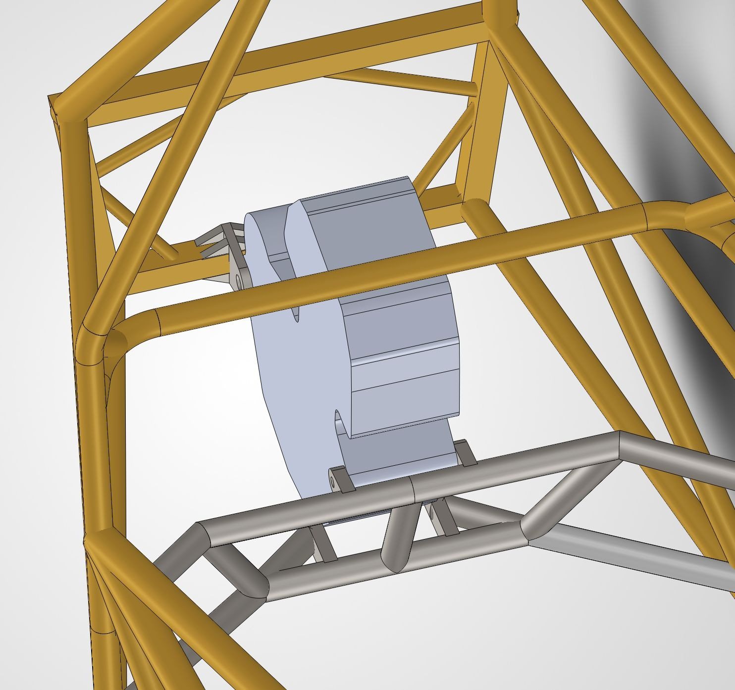
Designed an engine mount for the KTM 450 SX-F single-cylinder that powers Berkeley Formula Racing's car, as the chassis subteam's recruitment project. The brief was open-ended: learn the engine, work out what loads the mount has to survive, then design, simulate, specify the hardware, cost it and plan how to build it.
The final design is a triangulated cradle of 1 in × 0.120 in wall 4130 steel tube welded to the main chassis. It reaches a factor of safety of 2 with 0.3 mm maximum displacement, weighs about 10 lb, and costs $177 in material and hardware.
Requirements & Load Cases
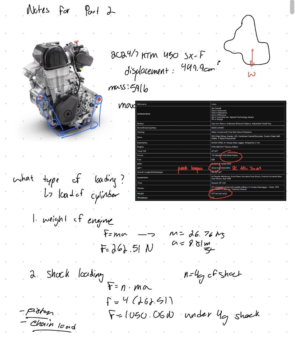
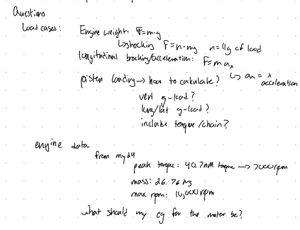
Started from the engine itself: using BFR's website and previous build data I pulled the KTM 450 SX-F's mass (26.76 kg), displacement (449.9 cm³) and torque curve, because every load on the mount traces back to them. The engine's weight alone is F = mg = 262.5 N; under a 4 g shock that becomes about 1,050 N. On top of that the mount sees chain pull, piston oscillation from the single cylinder, and lateral and longitudinal loads from cornering, braking and acceleration.
The rule I set myself was to question everything: why this and not that? Which load cases matter, what material and why, what hardware, can the engine still be removed, how much does it cost and how is it made. And keep it simple.
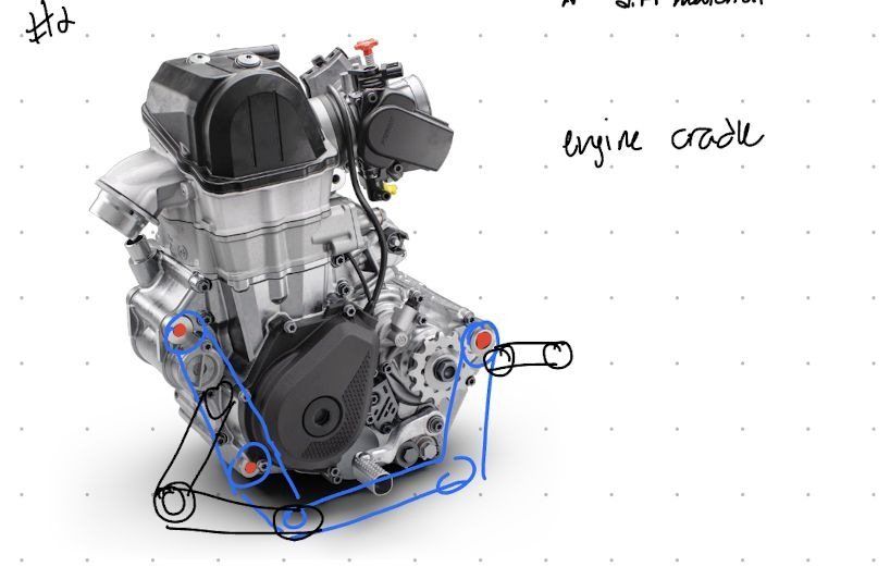
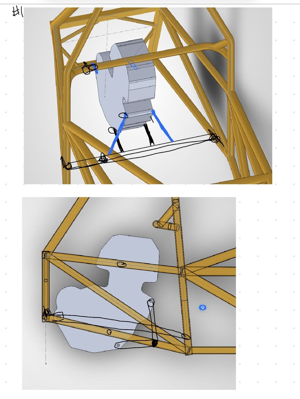
Sketches
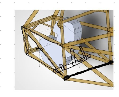
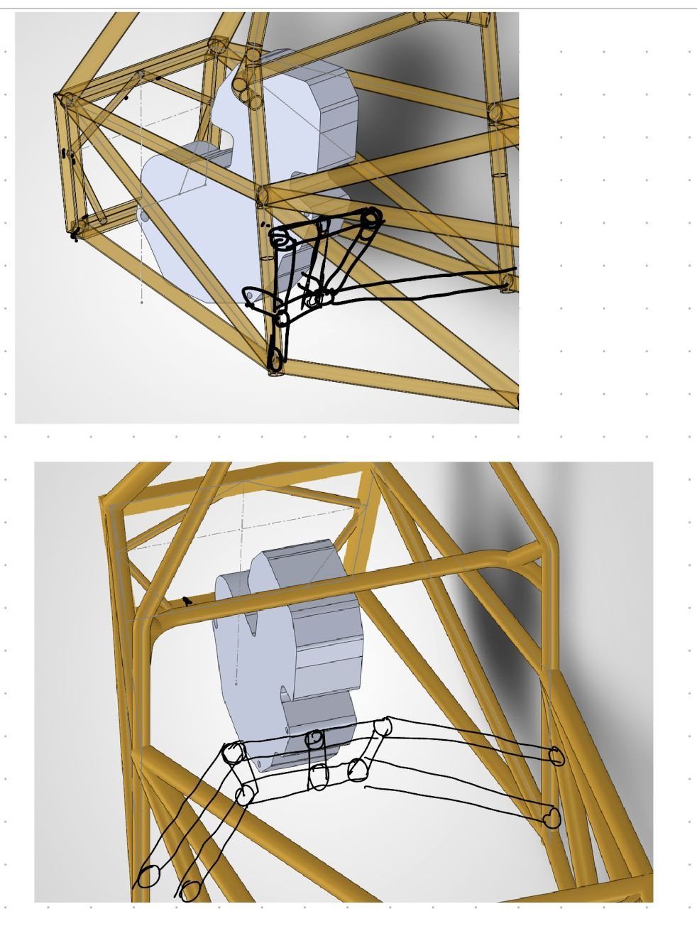
Ideas went on paper before CAD, sketched straight over the engine and the chassis model. The two things I cared about most were how the mount would carry the loads into the frame and how easy it would be to build. I took the sketches to office hours with the chassis leads to validate the direction before committing to a design.
First Iteration
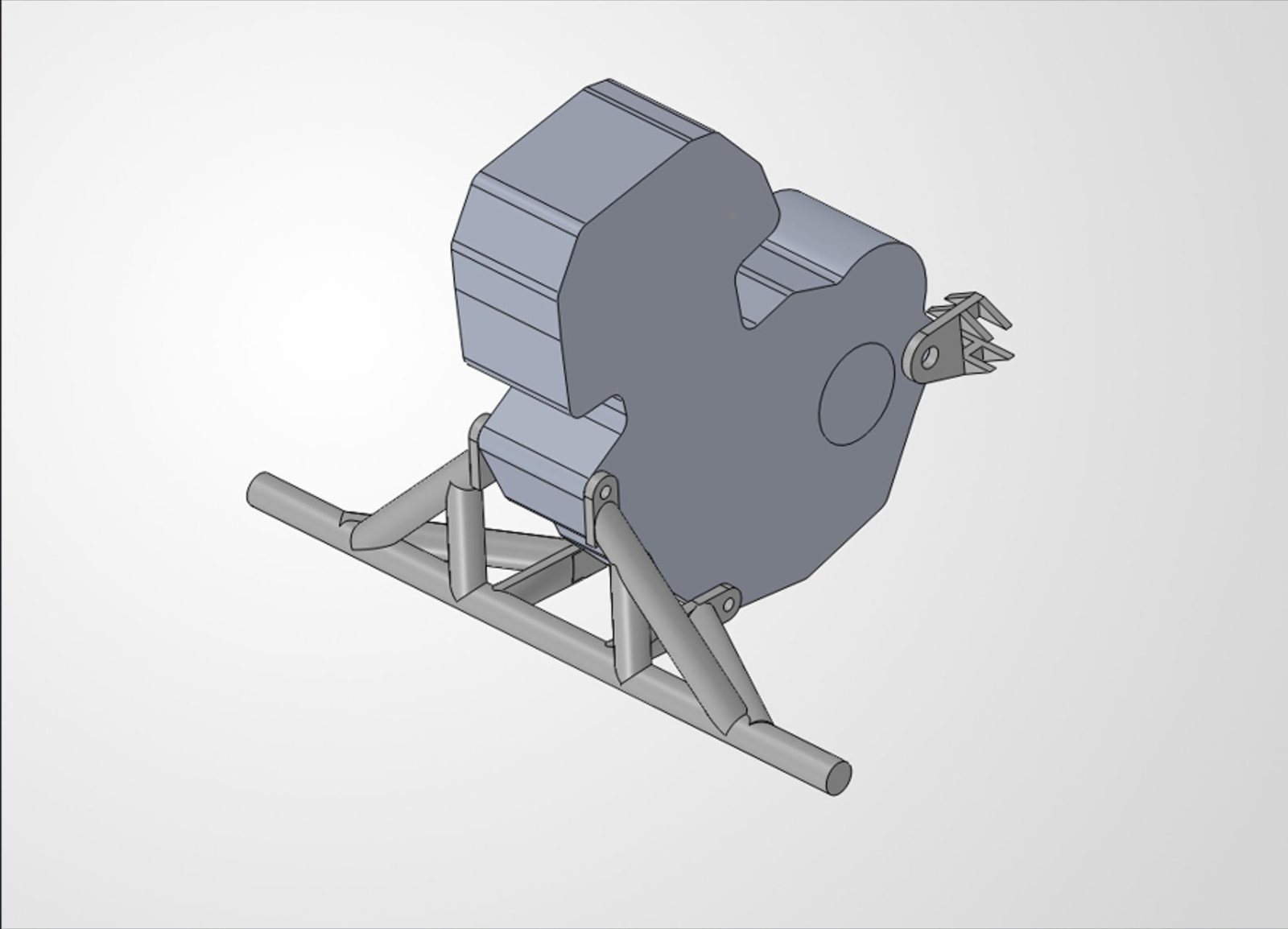
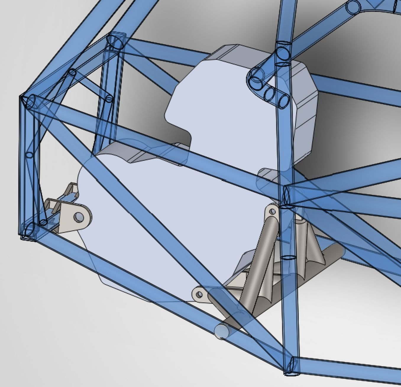
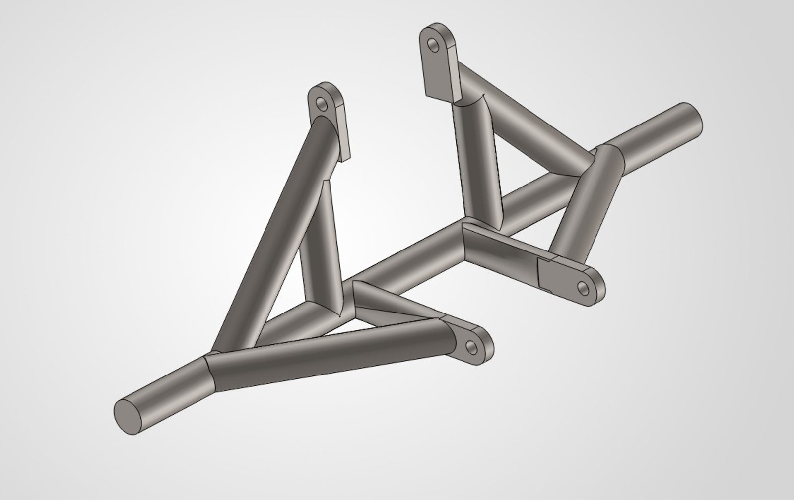
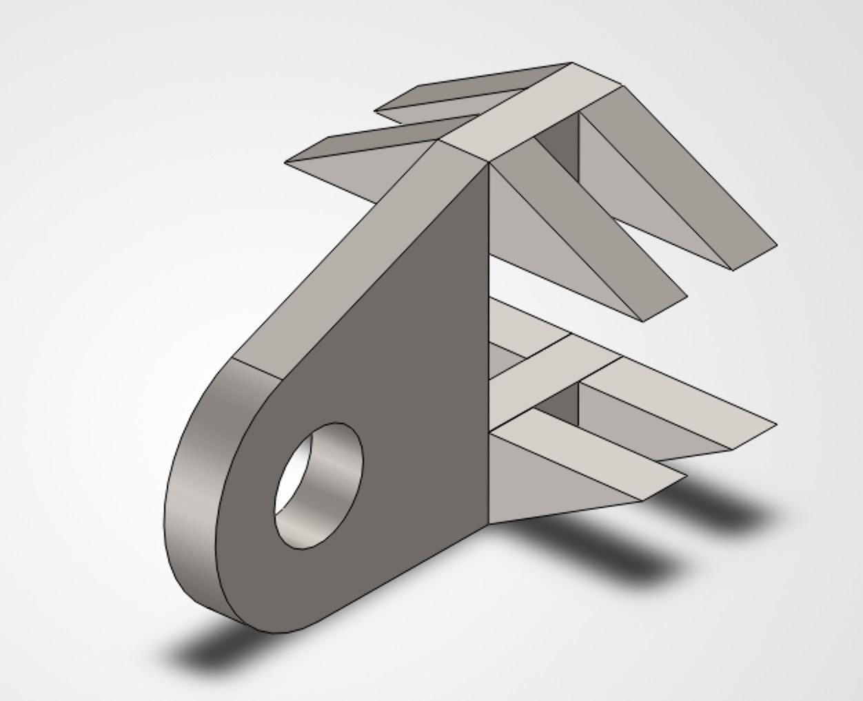
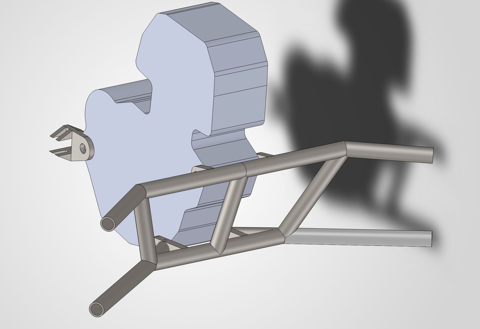
A tube-frame mount in 1 in OD, 0.76 in ID 4130 steel with ½ in flat tabs, welded to the main chassis and triangulated for stiffness. A separate machined bracket picks up the engine's rear mounting point. Total mass: 6.9 lb.
Simulation #1
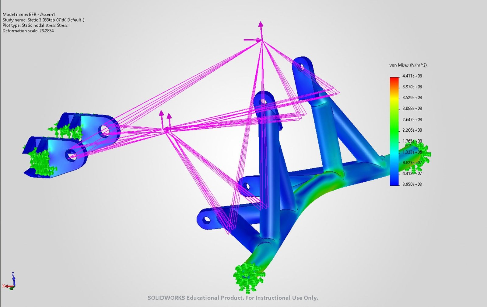
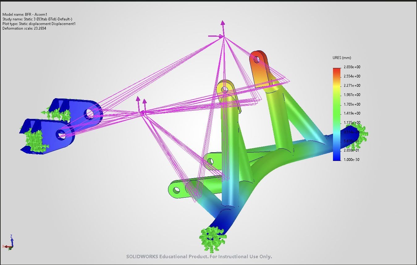
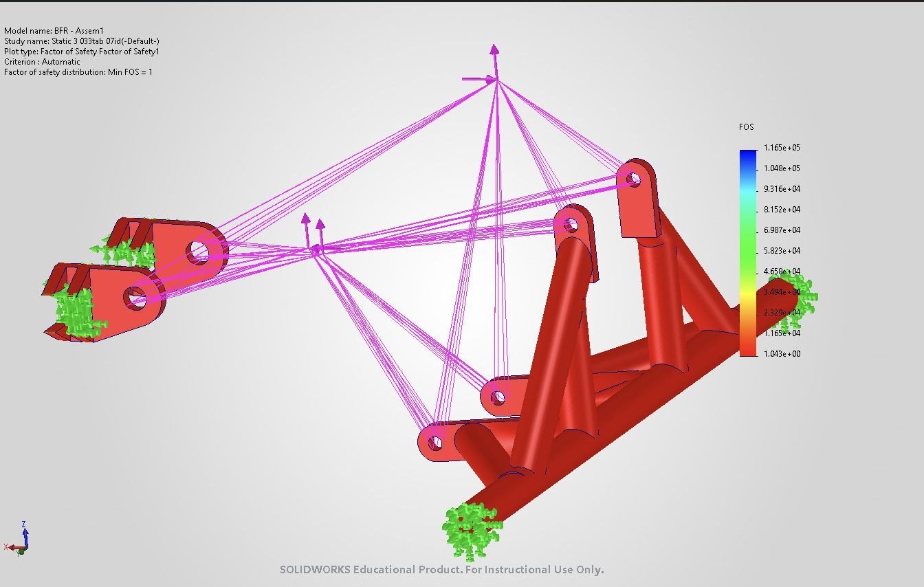
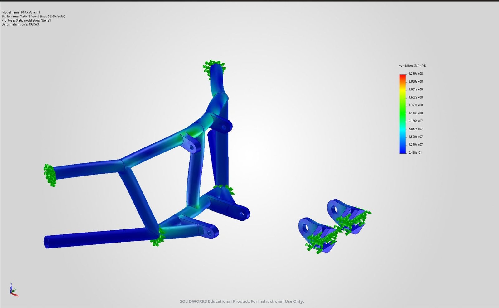
SolidWorks FEA on the assembly came back with a factor of safety of only 1 and 3 mm of maximum displacement, enough to risk yielding or structural damage. Not good enough, so back to the design.
Second Iteration
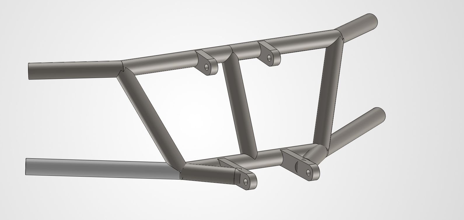
Added a top chassis mounting bar to tie the cradle into the frame and stiffen it, keeping the same tube size and material. The rear bracket was left alone because its displacement in the first run was already low. Total mass: 10 lb.
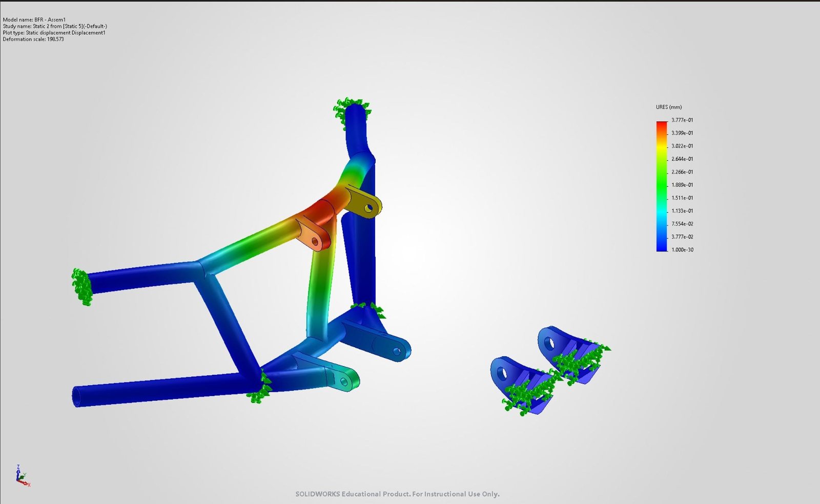
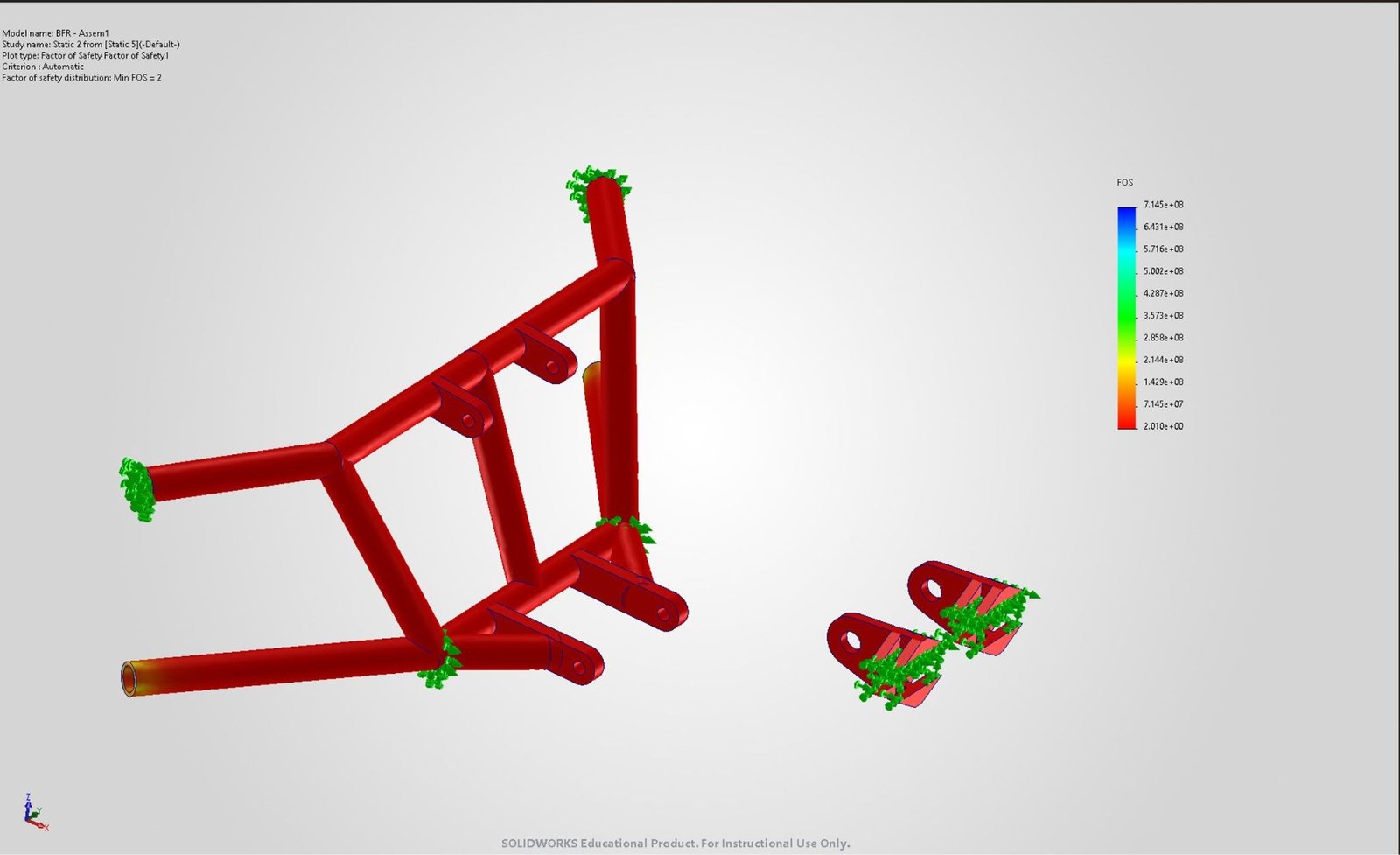
Simulation #2
- Factor of safety of 2, which meets the target
- Maximum displacement of 0.3 mm, ten times lower than the first iteration
- 43% heavier for a 100% increase in factor of safety. The next iteration should win some of that weight back
Material & Sizing
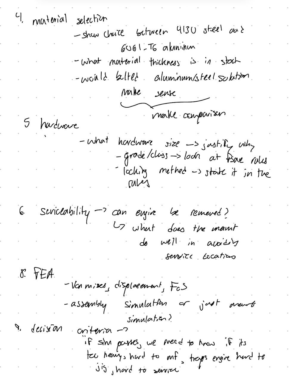
I compared 4130 steel against 6061 aluminum. Aluminum is much lighter, but it is only about a third as stiff (69 GPa against 200 GPa), so it needs larger tube sections for the same rigidity, and welding significantly weakens it in the heat-affected zone. 4130 also has a higher welded design strength in the FSAE material table. An engine mount has to resist torque, vibration and bending, so stiffness beats weight saving here. Staying in steel also avoids a steel-to-aluminum transition at the chassis and keeps the welding simple.
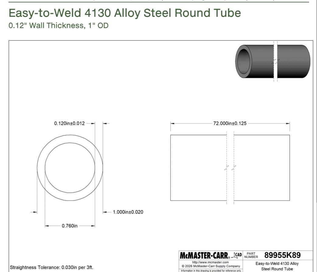
For sizing, 1.000 in OD × 0.120 in wall tube gives an area moment of inertia of 13,615 mm⁴, about 17% stiffer in bending than the same OD in 0.095 in wall, and it exceeds every FSAE Size A steel-tube minimum, a conservative structural baseline.
Hardware
- Front: 2 × M10 × 1.5, 130 mm, class 10.9, fits the 10.08 mm front holes, with length for the 4.50 in grip, washers, nut and thread projection
- Rear: 1 × M16 × 2.0, 140 mm, class 10.9, fits the 16.67 mm rear hole and gives a larger, stronger rear attachment
- Hardened steel washers on both sides of every joint to spread clamp load and stop the head and nut digging in
- All-metal prevailing-torque lock nuts for positive locking against vibration, and safer than nylon inserts next to engine heat
Cost & Manufacturing
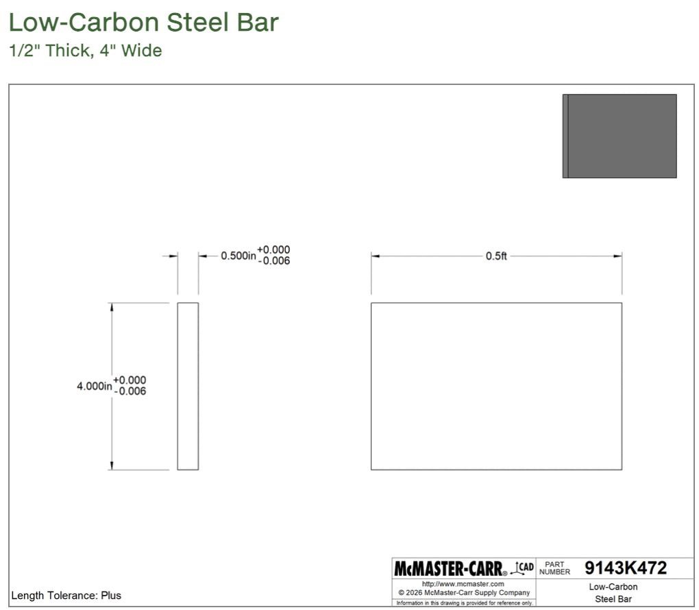
Material is 6 ft of 1.000 in OD × 0.760 in ID 4130 tube ($85.86, leaving 6 in spare for notching) and half a foot of ½ in × 4 in 1018 steel flat bar for the tabs ($20.89). 1018 is easy to cut, machine and weld. With hardware, the whole mount comes to $177.
To build it: cut the tubes to CAD length and notch the ends; laser- or waterjet-cut the tabs and drill and ream the bolt holes to final size; deburr and clean everything before welding; hold the tabs, tubes and hole locations in a welding jig; tack-weld in the jig and test-fit to the chassis and engine before any final welds; then finish-weld, prep and paint. Next steps are cutting weight while holding a factor of safety of at least 2, and a vibration and fatigue analysis, since a single-cylinder engine is exactly the load case where that matters.